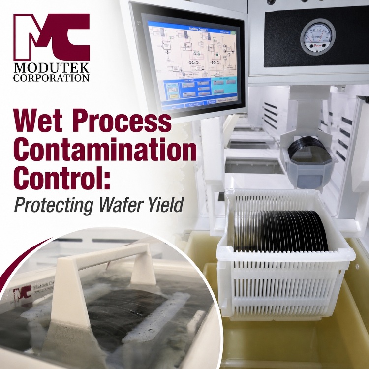
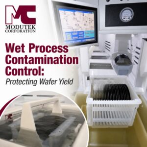
 Effective contamination control depends on disciplined process practices and equipment designed to isolate chemistries, supported by appropriate materials, ultrapure water, filtration, monitoring, and environmental controls. Modutek designs wet-process systems for semiconductor manufacturers, incorporating appropriate chemistry isolation according to each system’s process requirements.
Table of Contents
- Understanding Cross-Contamination Risks in Wet Process Environments
- Common Sources of Wafer Particle Contamination in Multi-Bath Systems
- Silicon Wafer Cleaning Best Practices for Multi-Chemical Bath Systems
- How Equipment Design Reduces Defect Density and Improves Wafer Yield
- HowModutekDesigns Wet Process Systems for Contamination Control
- Conclusion
- FAQs
Introduction
In semiconductor fabrication, a particle a fraction of a micron wide can destroy yield. Contamination control in wet process systems is not a secondary concern behind throughput or cost. It is one of the critical variables that can determine whether a batch of wafers proceeds, requires rework or is scrapped.
Wet-process environments that rely on multiple chemical baths and shared process lines carry inherent risks. Chemistry, hardware, and handling all interact, and a single weak point can introduce contaminants into the next step.
This article covers the practical mechanics of contamination control: where cross-contamination originates, how to prevent it through process discipline and megasonic cleaning, and why system design determines how much of that risk gets engineered out before a wafer ever enters a bath.
1. Understanding Cross-Contamination Risks in Wet Process Environments
Cross-contamination in wet bench processing is the unintended transfer of chemical residues, ions, or particles between process steps, baths, or substrates. This sounds narrow, but the consequences are not.
Multi-bath, multi-chemical sequences amplify the risk. Each transfer between baths is a chance for residue from the prior step to carry over, whether it rides on the wafer surface, the carrier, or the transfer mechanism itself. Shared process lines compound the problem. Common plumbing, rinse tanks, and recirculating loops accumulate residue over time, and that residue does not remain confined to a single chemistry.
The downstream effects show up in numbers process engineers and facilities managers track closely:
- Higher defect density across the wafer surface
- Lower yield per lot
- Failed QA inspections that trigger rework or scrap
- Higher production costs tied to both
Contamination control is critical to production output, internal quality requirements, and customer qualification procedures. Documented process control, chemical management, and contamination monitoring can also support internal quality requirements and customer qualification procedures. The hardest part of managing wet process contamination is that it is often invisible.
A bath can appear clean while still containing or accumulating submicron particles and ionic contaminants.
Yield data and particle counts are usually the first signal something is wrong, and by then the cost has already been incurred. Preventing contamination at the source is far cheaper than diagnosing it after the fact.
2. Common Sources of Wafer Particle Contamination in Multi-Bath Systems
Wafer particle control starts with knowing where contamination actually comes from. Most sources fall into a short list of recurring categories.
- Chemical carryover. Drag-out from one bath into the next, carried on the wafer, carrier, or robot arm, introduces foreign chemistry into the next step.
- Bath degradation. Chemical baths that go unmonitored or unrefreshed lose effectiveness over time and become sources of ionic or particulate contamination themselves.
- Inadequate rinsing. Insufficient DI water rinse steps between chemical baths leave residual chemistry on the wafer surface, where it can react with or contaminate the next process bath.
- Material off-gassing or leaching. Tank and plumbing materials that are not chemically compatible with the process chemistry can shed trace contaminants directly into the bath.
- Airborne particles. Open-bath configurations and inadequate enclosures expose substrates to ambient particulates, posing a greater risk outside a controlled cleanroom.
- Operator handling. Manual transfer steps introduce variability that automated systems substantially reduce, since human contact is a source of contamination every time a wafer changes hands.
Each of these sources is manageable on its own. The challenge is that most wet process lines are running simultaneously, and their effects compound. A bath running slightly out of spec is a minor issue. However, a bath running out of spec while also experiencing drag-out from inadequate upstream rinsing is a yield problem waiting to surface.
3. Silicon Wafer Cleaning Best Practices for Multi-Chemical Bath Systems
Preventing contamination in multi-bath systems comes down to sequencing, monitoring, and using the right tools for strongly adhered particles that chemical cleaning or rinsing alone may not remove effectively.
Start with chemical sequencing protocols, such as SC1 and SC2, that define the bath order to avoid incompatible chemical interactions and minimize the cross-contamination window. Follow each chemical step with a dedicated rinse stage. Cascading DI water rinse systems progressively remove residue, lowering particle counts before the next bath.
Megasonic cleaning belongs at critical points in that sequence. Megasonic systems use high-frequency acoustic energy to generate fluid motion and controlled cavitation-related forces in the cleaning liquid. These forces help overcome particle adhesion without direct mechanical contact with the wafer. Research at approximately 862 kHz demonstrated effective removal of submicron particles, with performance dependent on particle size, composition, chemistry, acoustic power, and cleaning time (Busnaina and Kashkoush, 1995).
Megasonic cleaning has also been evaluated on patterned silicon structures, which more closely represent actual device geometries than bare wafers. Testing at 0.96 MHz demonstrated effective particle removal, with performance and the risk of pattern damage influenced by solution chemistry, dissolved gases, and acoustic conditions (Sahoo et al., 2022).
| Megasonic Cleaning | At a Glance |
| Frequency range | 850 kHz to 2 MHz |
| Cleaning mechanism | High-frequency acoustic energy produces fluid motion and controlled cavitation-related forces that overcome particle adhesion at the wafer surface |
| Documented removal | Effective submicron-particle removal demonstrated near 862 kHz; results depend on particle properties and process conditions. (Busnaina and Kashkoush, 1995) |
| Patterned-wafer validation | Effective at 0.96 MHz; efficiency depends on bath chemistry (Sahoo et al., 2022) |
| Best suited for | Device structures too delicate for abrasive or contact-based cleaning |
A few additional practices round out an effective silicon wafer cleaning process:
- Monitor bath chemistry at intervals appropriate to the process, using continuous sensing and automated replenishment where supported by the system configuration.
- Assign tank-specific tooling and carriers; avoid moving them between incompatible chemistries without a full cleaning cycle.
- Many semiconductor facilities target ultrapure DI water approaching 18.2 MΩ·cm, depending on process requirements.
- Log particle counts, chemical concentrations, and rinse conductivity consistently so that contamination sources can be isolated quickly.
None of these practices work in isolation—sequencing without monitoring delays the discovery of a problem. Monitoring alone does not remove strongly adhered submicron particles; the cleaning method must be matched to the process requirements.
4. How Equipment Design Reduces Defect Density and Improves Wafer Yield
Process discipline only goes as far as the equipment allows. Systems engineered for chemical delivery isolation and precise particle control remove entire categories of risk before an operator ever touches a control panel.
| Manual Process | Engineered System | |
| Chemical isolation | Shared tanks and lines carry cross-contamination risk | Dedicated tanks, separate drain/exhaust lines, no shared wetted surfaces |
| Material compatibility | Standard materials can leach or degrade under chemical attack | PFA, PVDF, or high-purity polypropylene resist chemical attack and minimize material-derived contamination when properly matched to the chemistry |
| Sub-micron particle removal | Chemical rinsing alone is often insufficient for removing strongly adhered sub-micron particles | Integrated megasonic systems with application-appropriate frequency and adjustable process parameters |
| Chemical dispensing | Manual addition introduces concentration variability | Closed-loop, software-controlled dispensing |
| Wafer handling | Operator contact at every inter-bath transfer | Robotic transfer arms minimize manual handling and improve transfer consistency |
| Exhaust and ventilation | Ad hoc ventilation risks fume drift onto adjacent baths | Proper exhaust design minimizes airborne contamination and protects both process integrity and personnel |
| Process visibility | Spot-checks catch problems after they have already affected yield | Real-time sensor data can identify process deviations and abnormal bath conditions before they affect multiple wafer lots |
Chemical isolation by design, meaning dedicated tanks per chemistry, separate drain and exhaust lines, and no shared wetted surfaces, substantially reduces cross-contamination risk at the infrastructure level rather than relying on operators. Material compatibility underscores that tanks, fittings, and plumbing made from PFA, PVDF and high-purity polypropylene resist chemical attack and minimize material-derived contamination when properly matched to the process chemistry and operating conditions.
Integrated megasonic systems can be configured with an application-appropriate frequency and adjustable process parameters to accommodate different device geometries and chemistries. Careful control of power, cleaning time, chemistry, and dissolved gases helps balance particle removal with protection of fragile structures.
Automation closes the remaining gaps:
- Automated chemical dispensing. Closed-loop, software-controlled systems replace manual addition, reducing concentration variability associated with human error.
- Robotic wafer handling. Robotic transfer arms minimize routine operator handling during inter-bath transfers, thereby reducing a common source of contamination and process variability.
- Engineered exhaust and ventilation. Properly designed systems keep chemical fumes and aerosols from settling on wafer surfaces or drifting into adjacent baths, and reduce operator exposure to airborne chemistry.
Sensor-based data integration provides engineers with real-time visibility into bath conditions, enabling them to identify process deviations before they manifest as yield losses.
Equipment design does not replace process discipline. It determines how much discipline is actually achievable on the production floor.
5. HowModutekDesigns Wet Process Systems for Contamination Control
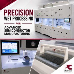
Modutek builds wet bench stations to customer specifications, with material selection, chemical compatibility, and process isolation designed from the start.
High-purity, chemically compatible tank and wetted-component materials, including PFA/PTFE, PVDF, polypropylene, and quartz, are used in Modutek’s systems in accordance with the process chemistry and operating requirements. Modutek’s automated wet bench systems use robotic transfer arms to minimize manual handling and associated contamination variability.
Wet bench systems can be configured with integrated megasonic cleaning, enabling sub-micron particle removal within the process sequence rather than a standalone tool. That reduces footprint, process complexity, and the risk of recontamination between steps. Depending on the system configuration, integrated chemical delivery and control systems can monitor bath conditions, manage replenishment, and record process data for traceability.
Modutek systems are tested at its facility before delivery, commonly using DI water. Customers can participate in Factory Acceptance Testing to verify agreed specifications and requirements before shipment. Modutek’s engineering and support teams remain involved throughout the full project lifecycle, from initial design specification to final acceptance and installation.
That relationship does not end at installation. Support continues through startup, troubleshooting and preventive-maintenance planning to help the system maintain specified performance over its service life.
6. Conclusion
Effective contamination control is achieved when disciplined process practices and well-engineered equipment work together. By combining optimized cleaning processes, including megasonic cleaning for challenging submicron particles, with wet process systems designed to isolate chemistries and reduce cross-contamination, semiconductor manufacturers can improve wafer yield, reduce defects, and achieve more consistent process performance.
The business case is straightforward. Lower particle contamination means lower defect density, and lower defect density means more usable wafers per lot. When particle contamination is a significant source of defects, improved contamination control can increase usable wafer output and directly contribute to manufacturing ROI.
Explore how Modutek’s semiconductor wet process solutions, including integrated megasonic cleaning options, are engineered to minimize contamination risks. Contact Modutek’s team to discuss your process requirements or request a system consultation.
7. FAQs
Q1. What causes cross-contamination in wet process systems?
Cross-contamination happens when chemical residues, ionic species, or particles from one process step transfer to the next. Common causes include chemical drag-out on wafer surfaces or carriers, inadequate rinsing, degraded baths, and shared plumbing or drain lines.
Q2. How does particle contamination affect defect density and wafer yield?
Particle contamination interferes with lithography, etching, deposition, and diffusion steps, reducing the number of functional dies per wafer. Even submicron particles can cause critical-dimension failures or electrical shorts. Controlling wafer particle contamination is directly tied to defect density and yield.
Q3. What are the most effective silicon wafer cleaning methods for multi-chemical bath systems?
Effective cleaning depends on chemical sequencing, dedicated rinse stages with high-resistivity DI water, real-time monitoring, and automated replenishment. Megasonic cleaning can improve the removal of strongly adhered submicron particles when chemical cleaning or rinsing alone is insufficient.
Q4. What is megasonic cleaning and how does it reduce particle contamination on wafers?
Megasonic cleaning uses high-frequency acoustic energy, typically between 850 kHz and 2 MHz in Modutek applications, to produce fluid motion and controlled cavitation-related forces in the cleaning liquid. These forces help overcome particle adhesion without direct mechanical contact with the wafer. Frequency, chemistry, dissolved gases, and acoustic power must be controlled to balance particle removal with protection of delicate structures.
Q5. Can equipment design reduce cross-contamination risks, or is it purely a process control issue?
Both matter, but equipment design is a foundational control. Systems engineered with chemical isolation, separate tanks, independent drain lines, and dedicated exhaust substantially reduce several major categories of risk that process protocols alone cannot address. Integrated megasonic capability, material selection, robotic handling, and closed-loop chemical delivery reduce contamination risk and lessen the process’s dependence on manual operator actions.
Q6. What should I look for in a wet process system designed for contamination control?
Key features to evaluate:
- Chemically isolated tank configurations with no shared wetted surfaces between incompatible chemistries
- High-purity construction materials such as PFA, PVDF, or polypropylene
- Integrated megasonic cleaning for sub-micron particle removal
- Automated chemical delivery and bath monitoring
- Robotic wafer transfer to minimize manual handling and contamination variability
- Documented pre-delivery testing and Factory Acceptance Testing procedures
References:
- Busnaina, A. A., and Kashkoush, I. I. “An Experimental Study of Megasonic Cleaning of Silicon Wafers.” Journal of the Electrochemical Society, Vol. 142, No. 8, 1995. DOI information is indexed by the Harvard Astrophysics Data System.
- Sahoo, B. N., et al. “Chemically Controlled Megasonic Cleaning of Patterned Structures Using Solutions with Dissolved Gas and Surfactant.” Ultrasonics Sonochemistry, Vol. 82, 2022, Article 105859.